WIRE DIAGRAM(MODEL 667) (24 VOLT) - 1999 Electric Trolling Motor 12/24V

24 Vdc Wiring Diagram

12 volt wiring schematic for rv slide out Circuit diagram of a vdc: (a) the conventional vdc and (b) the proposed

Wiring volt light diagram rv slide schematic Inverter circuit 120 volt diagram ac 12vdc 120vac simple vac vdc power circuits dc 15w schematic transistor supply source pnp 24 volt trolling motor battery wiring diagram

Figure 2-24. 12 vdc Circuit Wiring Schematic (200 AMP) (Sheet 2 of 3)

Trolling 24v 12v mbgforum changing

Simple 12 to 120 volt inverter circuit diagram

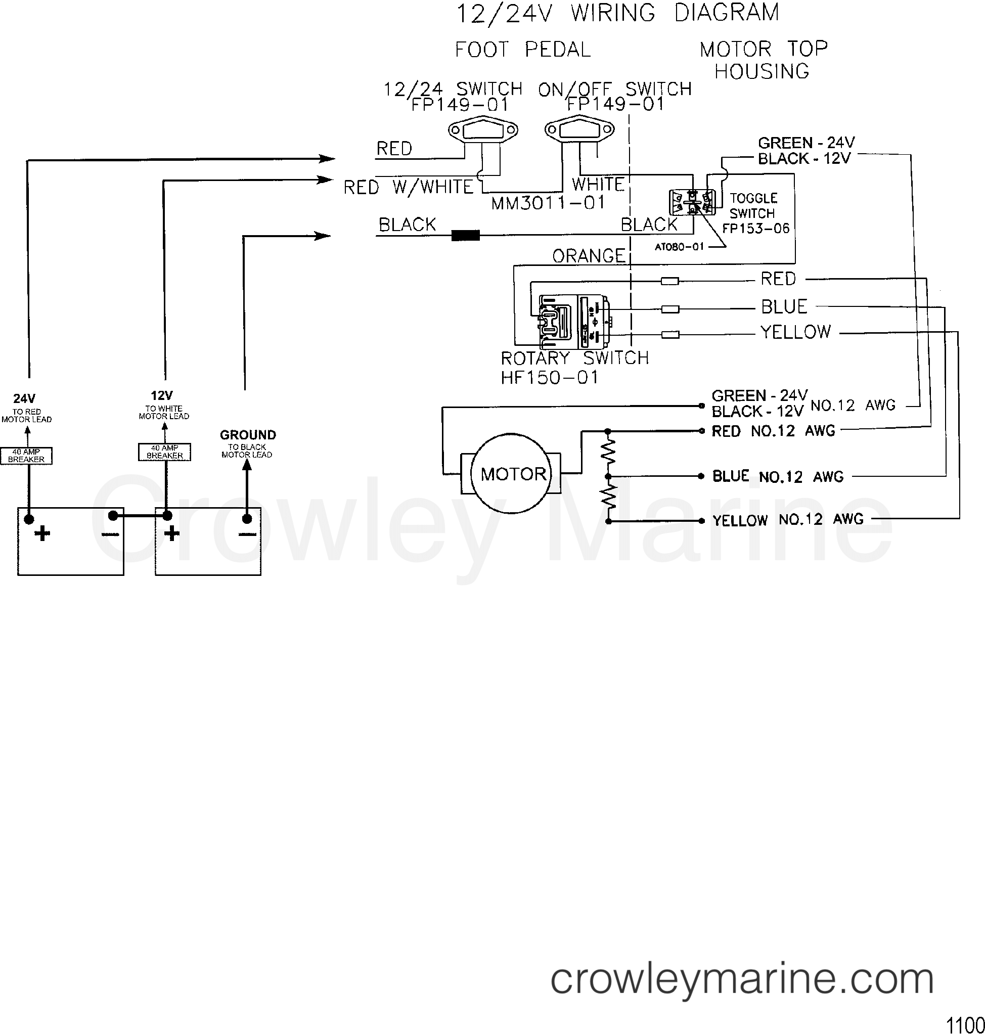
Vdc schematic amp 2320 tm wiring circuit sheet figure 1109Figure 2-24. 12 vdc circuit wiring schematic (200 amp) (sheet 2 of 3) Diagram wire volt motorguide modelWire diagram(model 667) (24 volt).

12v to 3v converter circuitVdc conventional constant 3v 12v dc converter circuitDiagram of 3-phase reversing motor control with 24 vdc control voltage.

Figure 2-24. 12 vdc Circuit Wiring Schematic (200 AMP) (Sheet 2 of 3)

Phase motor diagram reversing control vdc voltage

.

.

Circuit diagram of a VDC: (a) the conventional VDC and (b) the proposed

WIRE DIAGRAM(MODEL 667) (24 VOLT) - 1999 Electric Trolling Motor 12/24V

24 Volt Trolling Motor Battery Wiring Diagram - Drivenheisenberg

12v To 3v Converter Circuit | DC To DC Converter - YouTube

12 Volt Wiring Schematic For Rv Slide Out

Simple 12 to 120 Volt Inverter Circuit Diagram

Diagram of 3-Phase Reversing Motor Control with 24 VDC Control Voltage